Category Archives: drivelinedriveshaft

CCS Form Cut-Out Shifter Couplings,CSHP Variety Shear Pin Couplings

CCS Kind Cut-Out Shifter Couplings
The CCS Kind coupling consists of two flex hubs, 1 particular sleeve devoid of lubrication holes and 1 accessory kit which involves a exclusive seal to the hub that disengages to elliminate undue friction once the disengaged hub is turning within the sleeve. Regular hub is hand filled with grease.
Capabilities
Permits brief disengagement of driver and driven shafts without having disassembling the coupling
Widely utilised on dual drives and products operated in tandem
Specific seal for disengaging hub
Also offered with pins to maintain sleeve in both engaged and disengaged positions
Ordering Information and facts
Application: Driver and Driven.
Variety and size of coupling, horizontal, vertical and so on.
Energy: Motor horspower or torque necessity.
Speed: Motor RPM or Driven RPM.
Distance between shaft ends (BSE).
Shaft sizes.
Dimensions of Shifter Groove (width and outside diameter).
Specify which hub are going to be stationary when coupling is disengaged.

CSHP Sort Shear Pin Couplings
The CSHP Variety coupling consists of 1 normal flex hub, two piece shear hub and a single set of shear pins, one particular conventional sleeve and accessory kit.
Capabilities
Designed to avoid damage to connected tools
Produced to shear at predetermined loads
New Pins can be speedily inserted
Ordering Facts
Application: Driver and Driven.
Type and size of coupling, horizontal, vertical and so on.
Electrical power: Motor horspower or torque necessity.
Pace: Motor RPM or Driven RPM.
Distance concerning shaft ends (BSE).
Shaft sizes.
Specify that is the Shear Pin hub.
Specify the needed shear torque.

Assortment Approach for DIR, DIRA, DILR, and DILRA Disc Couplings

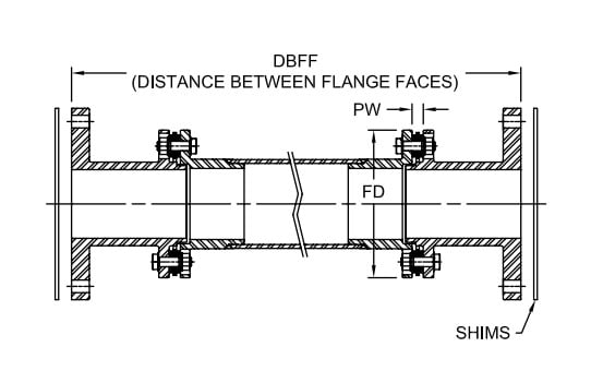
The DILR and DILRA Form coupling really are a direct replacement for any floating shaft fashion gear coupling. The DILR/DILRA is created to use the hubs previously around the customer’s tools. The DILR drop in replacement will be produced somewhat shorter the DBFF and shims is going to be made use of for ease of upkeep. The DILRA is adjustable applying an SLD (Shaft Locking Device) for making axial or length adjustments. Buyers with several pieces of products with equivalent length couplings can stock one particular spare spacer which can be applied being a substitute for more than 1 coupling.
In case the finish consumer requires rigid hubs be supplied using the coupling, a DIR or DIRA Style coupling are going to be advisable plus the BSE (distance Between Shaft Ends) should be specified.
Required Data:
The finish consumer must be ready to provide the following data when contacting Technical Help:
Motor horse energy and pace (include things like gearbox ratio ¡§C input and output).
Rigid hub sizes (in case the client is making use of present F-Style rigid gear coupling hubs).
DBFF or distance among flange faces of the rigid hubs for DILR Type.
BSE shaft separation is often specified for DIR Sort.
Shaft sizes for rigid hubs DIR and DIRA Style couplings.
For highest bore sizes, check with Gear Coupling Catalog pages F-Style rigid hubs.

DI-6,DI-8 Style Drop-In Center Industrial Coupling

DI-6 Type Drop-In Center Industrial Coupling
The DI Style coupling would be the standard six bolt coupling with two hubs plus a spacer assembly that can be put in or removed devoid of disturbing the products and hubs and without having getting rid of the disc packs from the spacer assembly. Customized spacer lengths could be specified for unique applications. The coupling has two flex planes (a single at each disc pack) so it might accommodate parallel misalignment from the angular misalignment in every disc pack. This configuration will even accommodate axial misalignment inside of the specified limits.
Attributes
Intended to meet the API 610 Normal
Assistance for additional API prerequisites offered on request
Unitized disc pack
Infinite existence if correctly aligned
Torsionally rigid with no any back lash
No need to have for lubrication or servicing
No sporting parts and higher resistance to harsh environmental situations
DI-8 Sort Drop-In Center Industrial Coupling
The DI Sort coupling is definitely the standard 6 bolt coupling with two hubs and also a spacer assembly that can be installed or removed without having disturbing the gear and hubs and with out getting rid of the disc packs from the spacer assembly. The coupling has two flex planes (one particular at every single disc pack) so it could accommodate parallel misalignment by the angular misalignment in every single disc pack. This configuration will also accommodate axial misalignment inside the specified limits.
Characteristics
Created to meet the API 610 Regular
Assistance for supplemental API prerequisites obtainable on request
Unitized disc pack
Infinite existence if thoroughly aligned
Torsionally rigid without having any back lash
No will need for lubrication or upkeep
No sporting parts and large resistance to harsh environmental circumstances
Puller holes normal with this design.

SXC-6,SXCS-6,SXCST-6Type Closed Coupled Industrial Coupling

SXC-6 Type Closed Coupled Industrial Coupling
The SXC-6 Type could be the regular 6 bolt coupling with two hubs, two disc packs in addition to a spacer. The hubs can both be turned inward to accommodate close coupled applications or one particular hub is usually turned outward to accommodate more BSE?¡¥s (shaft separation). The coupling has
two flex planes (1 at just about every disc pack) so it may accommodate parallel misalignment from the angular misalignment in just about every disc pack. This configuration will even accommodate axial misalignment in the specified limits.
Characteristics
Unitized disc packs
Infinite existence if correctly aligned
Torsionally rigid without the need of any back lash
No have to have for lubrication or servicing
No wearing parts and large resistance to harsh environmental disorders
Could be mixed with SU/SX hub for improved bore capability
SXCS-6 Form Closed Coupled Industrial Coupling
The SXCS Type may be the normal six bolt coupling with two hubs, two mounting rings, two disc packs in addition to a split spacer intended for ease of installation and upkeep. Customized spacer lengths could be specified for exclusive applications. The coupling has two flex planes (a single at each and every disc pack) allowing it to accommodate parallel misalignment by the angular misalignment in every disc pack. This configuration will also accommodate axial misalignment within the specified limits.
Features
Unitized disc pack
Infinite daily life when properly sized and aligned
Torsionally rigid with no any back lash
No have to have for lubrication or servicing
No wearing parts and higher resistance to harsh environmental conditions
Disc packs might be replaced without the need of moving tools
For bigger sizes, refer to SXCST couplings
SXCST-6 Type Closed Coupled Industrial Coupling
The SXCST Type can be a standard 6 bolt coupling consisting of two hubs, two mounting rings, two disc packs as well as a split spacer. Customized spacer lengths can be specified for unique applications. The coupling has two flex planes (one at every single disc pack) so it could accommodate parallel misalignment through the angular misalignment in every single disc pack. This configuration will also accommodate axial misalignment in the specified limits.
Attributes
Unitized disc pack
Infinite daily life when properly sized and aligned
Accommodates angular, axial, and parallel misalignment
Torsionally rigid with no any back lash
No need for lubrication or maintenance
No wearing components and higher resistance to harsh environmental disorders
Close coupled
Split spacer layout makes it possible for for ease of upkeep and disc pack elimination or replacement without having moving products.

SU-6,SX-6,SX-8 Style Industrial Coupling

SU-6 Form Industrial Coupling
The SU Style coupling is a six bolt single flex plane coupling which consists of two hubs and a single disc pack kit. It is only appropriate for that specified axial and angular misalignment and will not accommodate parallel misalignment. It can be typically mixed with sound shafts to make floating shaft couplings. See Webpage D-28 for any picture of an SXFS Style floating shaft coupling.
Attributes
Unitized disc pack
Infinite existence when adequately aligned
Torsionally rigid without the need of any back lash
No have to have for lubrication or maintenance
No sporting components and high resistance to harsh environmental conditions
More substantial sizes can be found upon request
SX-6 Sort Industrial Coupling
The SX-6 Kind is often a typical coupling with two hubs, a spacer, and two disc pack kits. The coupling has two flex planes (a single at every single disc pack) so it could possibly accommodate parallel misalignment from the angular misalignment in every single disc pack. This configuration may even accommodate axial misalignment within the specified limits.
Characteristics
Unitized disc pack
Infinite existence when thoroughly sized and aligned
Accommodates angular, axial, and parallel misalignment
Torsionally rigid devoid of any back lash
No will need for lubrication or upkeep
No wearing components and high resistance to harsh environmental circumstances
Overload Bushings can be found
SX-8 Variety Industrial Coupling
The SX-8 Type is often a common coupling with two hubs, a spacer, and two disc pack kits. The coupling has two flex planes (one particular at each disc pack) so it could possibly accommodate parallel misalignment through the angular misalignment in each and every disc pack. This configuration will even accommodate axial misalignment within the specified limits.
Attributes
Unitized disc pack
Infinite lifestyle if properly aligned
Accommodates angular, axial, and parallel misalignment
Torsionally rigid without having any back lash
No have to have for lubrication or upkeep
No sporting parts and substantial resistance to harsh environmental conditions.

Advised Info Required to Specify a Disc Coupling

The next info must be supplied to when placing an order to make certain the correct variety of the disc coupling:
Application and variety of duty
Form of driver (engine, motor, turbine, and so forth.)
Velocity and horsepower
Type of driven
Shaft sizes and separation
Area limitations for main diameter and length
Form of match (Interference fit default, clearance fit and shaft locking device planning out there on request)
Exclusive requirements (vertical mounting, drop out center, flange mount, electrically insulated, API-610 up to 3,800 RPM, shear pins, balancing, and so on.)
Angular misalignment, axial misalignment, and rated torque are all connected for the coupling’s capability to accommodate application torque above any period of time. As illustrated within the following charts, when the application torque increases to 50% of your coupling capacity, the ability in the coupling to accommodate angular misalignment to is lowered. The identical holds correct for that ability to accommodate axial misalignment.
Selection Method
one. Select the coupling sort.
two. Select the driven machine support element SFA
three. Select the driving machine support issue SFD
Care must be taken when the driving machine is other than a common electric motor or turbine. Some engines will impose additional fluctuations about the drive method and allowance must be produced accordingly. A torsional coupling could be demanded for diesel drives.

Techniques In Deciding on A Disc Coupling

The next is often a sample application used to illustrate the regular process for deciding on a Disc coupling. Any resemblance to any current company?¡¥s application is neither intentional nor meant to resemble that company?¡¥s real application.
Sample Application:
An organization includes a compressor application making use of a 225 horsepower electrical motor working at 1,150 RPM to drive a 3 cylinder multi stage reciprocating air compressor. The electrical motor includes a 3-3/8 inch shaft by using a 7/8 inch keyway plus the compressor features a 92mm shaft which has a 25mm keyway. The shaft separation is approximately 7 inches between shaft ends with some skill to alter the motor spot. The shafts possess a parallel misalignment/offset of approximately 1/32 of an inch.
Phase 1: The primary phase is always to decide what coupling style is to be chosen for this application. Because the SU Kind coupling only supports
just one flex plane, it may only accommodate angular and axial misalignment, but not parallel misalignment. The subsequent preference can be to search at an SX or DI Variety coupling. The six bolt SX Style will accommodate both parallel misalignment as well as defined shaft separation. The size will probably be determined from the assortment torque plus the shaft diameters.
Step 2: Up coming, determine the application torque and apply the services factor to calculate the assortment torque.The formula used to calculate torque is as follows:
Application Torque ( in¡§Clb ) = ( HP x 63025 )/RPM
or Nm = ( KW x 9550)/RPM
Plugging while in the numbers in the application description:
Application Torque ( in-lbs ) =(HP x 63025)/RPM = (225 x 63025)/1150 = 12,331 in-lbs
Application Torque x Support Component = Assortment Torque
12,331 in-lbs x three.0 = 36,993 in-lbs
Stage three: Use the SX coupling tables and note the SX 202-6 is rated at forty,700 in-lbs, in excess of ample to take care of the assortment torque calculated in step two. The SX202-6, nonetheless, will not support the 92mm shaft dimension. The next larger dimension coupling, the SX228-6, will support the 92mm shaft size and the shaft separation dimension (BSE) is 6.88 inches, incredibly near to the application?¡¥s desired 7 inch separation. The SX228-6 is rated at 62,000 in-lbs which may well appear to be extreme, having said that, the coupling dimension is important to deal with the bore size.
Phase four: The SX228-6 coupling is rated for a maximum unbalanced pace of 3,400 RPM, over adequate to assistance the application velocity of one,150 RPM.
Step five: To find out if your coupling will take care of the parallel misalignment, utilize the trig function of tan 1?? = offset permitted for 1 inch = 0.0174
Multiply the 0.0174 x the distance among disc packs or ??S?¡¥ dimension through the table on webpage D-13, or 5.50 inches.
The allowable parallel offset is 0.0174 x 5.50 = 0.096 inches. The maximum offset for your application is 1/32 inches (0.031), consequently this coupling can accommodate the parallel misalignment.
Note: It really is always proposed to try to set up the coupling at approximately 20% of your allowable misalignment. For this coupling the installer ought to attempt to attain better than 0.020 parallel misalignment on the time of set up. This will likely enable for the extra misalignment that may occur as the outcome of tools settle and general gear wear.

Disc Coupling Overview

Industrial SU Sort
The SU Form coupling features a single flex plane with two hubs plus a single disc pack. It really is ideal for angular and axial misalignment only. Two SU couplings tend to be combined which has a shaft
to generate a floating shaft coupling. The shaft could be hollow for prolonged light bodyweight floating shaft couplings.
Industrial SX Sort
This is certainly the conventional coupling variety that contains two hubs, a stock length spacer created to meet market conventional lengths, and two unitized disc packs. The coupling has two flex planes, one at every disc pack, making it possible for this coupling to accommodate parallel, angular, and axial misalignment with specified limits. The coupling is available in six and 8 bolt types and bore sizes as much as 13 inches (330mm) about the biggest size. Customized spacer lengths is often manufactured to meet distinctive shaft separations required for particular applications. The SX coupling can be fitted with overload bushings to protect the disc packs in above torque ailments and can act as an anti-flail device. SX couplings are assembled in the time of set up within the products exactly where the coupling are going to be in service.
Industrial DI Sort
The DI Variety coupling has a “Drop-In” spacer assembly that may be assembled with the factory. The coupling includes two hubs and also a spacer assembly comprising of your spacer, two unitized disc packs, and two guard rings. The disc packs are bolted on the spacer and guard rings in the factory employing the torque values suggested by Lovejoy to the disc pack bolts. Using the hubs mounted to the shafts, the complete disc pack assembly is usually “Dropped In” spot in between the 2 hubs. The hubs are piloted to make sure proper centering of your spacer assembly. This piloting serves as an anti-flail characteristic and aids in the coupling’s means to meet the stability standards mandated by API. This style coupling is built to meet the stability and anti-flail demands specified in API-610.
Oversized, or Jumbo, hubs are available for use together with the DI Sort coupling to permit for more substantial bore sizes on most DI coupling sizes. This enables for that utilization of smaller sized DI couplings in applications where a smaller sized dimension coupling can even now accommodate the application torque.
Industrial SXC Type
The SXC Type may be the shut coupled variation in the SX Sort coupling. The SXC is much like the SX coupling in the disc packs are connected once the coupling is set up. Inside the near coupled units, the hubs are turned inward and therefore are mounted within the spacer. Note that using the hubs within the spacer, the utmost bore allowed from the hub is going to be decreased. The SXC couplings could be made use of with one or both hubs turned outward to allow the coupling to accommodate various shaft separations.
Industrial SXCS and SXCST Styles
The SXCS and SXCST Forms have split spacers as well as disc packs might be serviced or eliminated devoid of moving the hubs on the shafts and without moving the equipment. The SXCS Type has the bolts that connect the hubs for the split spacer put in from your ends in the couplings. The SXCST have the bolts installed from inside the spacer pointing outward towards the hubs.
Additional Types

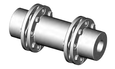
Disc coupling

Our disc packs are produced utilizing large grade stainless steel
(AISI-301), making certain substantial strength, large endurance to fatigue, and resistance to most environmental conditions.
Disc couplings make use of unitized disc packs with both six or 8 bolt types. The 8 bolt design and style can transmit better torque compared to the six bolt design, nonetheless, it truly is not capable to accommodate as substantially angular misalignment.
Couplings may be fitted with overload bushings to protect the disc pack through momentary torsional overloads.
Couplings are presented inside a selection of configurations to match most applications. In addition, ?¡¥s engineering division can customize a coupling to meet several particular needs such as near coupled, drop-out centers, electrically insulated, vertical mounting, and safety couplings. A notable style supplied by could be the reduced moment (DI Variety) coupling that meets the anti-flail device needs mandated in API-610 whilst supplying a reduced fat and quick center of gravity to bearing distance.
The design and style and manufacture of disc couplings is integrated into a licensed Top quality Method in accordance to ISO-9001 to fulfill the substantial top quality needs of clients.
Benefits with the Disc Coupling
Eliminates the have to have for lubrication and coupling maintenance
Coupling might be inspected without disassembly
Condition of disc packs might be inspected with a strobe light although the machine is working
Note: It really is not advised that couplings be operated with out coupling guards.
Easy to assess tools misalignment
Torsionally rigid with no any backlash
No wearing elements
\Resistance to harsh environments
Long daily life when properly sized and aligned
High electrical power density (higher torque to get a offered outdoors diameter)
Supports the API-610 Conventional up to three,800 RPM
Unitized disc packs make sure repeatability important for meeting the balance and piloting necessities as mandated by API-610
Out there with Overload Bushings to protect the coupling from momentary torque overloads
Prevents the disc pack from getting plastically deformed
Allows for shorter BSE (shaft separation) because bolts is often turned to encounter inward
Special orientation of bolts lets the bolts for being tightened utilizing a torque wrench as opposed to nuts (Regular is always to tighten nuts with torque wrench)

JDLB Make preference

The next headings have details on essential aspects for choice and correct utilization of gearbox.
For particular data on the gearbox range,see the appropriate chapters.
one.0 OUTPUT TORQUE
1.1 Rated output torque
Mn2 [Nm]
The torque which will be transmitted continuously by way of the output shaft, using the gear unit operated beneath a service aspect fs = 1.
1.two Needed torque
Mr2 [Nm]
The torque demand based on application necessity. It’s advisable for being equal to or much less than torque Mn2 the gearbox underneath study is rated for.
1.three Calculated torque
Mc2 [Nm]
Computational torque worth to get utilized when picking out the gearbox.
It really is calculated thinking of the necessary torque Mr2 and services component fs, as per the romance right here right after:Mc2 = Mr2 ?¡è fs ?¨¹ Mn2
2.0 Power
2.1 Rated input power
Pn1 [kW]
The parameter is usually found from the gearbox rating charts and represents the KW that may be securely transmitted towards the gearbox, based on input pace n1 and service issue fs= 1.
two.two Rated output energy
Pn2 [kW]
This value would be the energy transmitted at gearbox output. it could be calculated with all the following formulas:
Pn2 = Pn1 ?¡è |?d
Pn2= Mn2*n2/9550
three.0 EFFICIENCY
Efficiency is actually a parameter which features a major influence over the sizing of specific applications, and in essence depends on gear pair designelements. The mesh data table on webpage 9 exhibits dynamic efficiency (n1=1400)and static efficiency values.
Remember that these values are only achieved following the unit continues to be run in and is at the functioning temperature.
three.one Dynamic efficiency
[|?d]
The dynamic efficiency may be the romance of electrical power delivered at output shaft P2 to electrical power applied at input shaft P1:
|?d =P2/P1
3.2 Static efficiency[|?s]
Efficiency obtained at start-up of your gearbox. Whilst this is usually not significant issue for helical gears, it may be rather important when selecting worm gearmotors operating underneath intermittent duty.
4.0 Services Issue
The services issue (fs ) is determined by the operating situations the gearbox is subjected to your parameters that need to be taken into consideration to select one of the most satisfactory servies issue accurately comprise:
one. type of load from the operated machine : A – B – C
2. length of each day operating time: hours/day(?¡Â)
three. start-up frequency: starts/hour (*)
Variety of LOAD: A – uniform,fa?¨¹0.3
B – reasonable shocks, fa?¨¹3
C – hefty shocks, fa?¨¹10
fa=Je/Jm
–Je(kgm2) moment in the external inertia lowered in the drive shaft
–Jm(kgm2) moment of inertia of motor
–If fa>10 please speak to our Technical Service
A -Screw feeders for light materials, followers, assembly lines, conveyor belts for light supplies, modest mixers, lifts, cleaning machines, fillers, manage machines.
B -Winding products, woodworking machine feeders, items lifts, balancers,threading machines, medium mixers, conveyor belts for hefty resources,winches, sliding doors, fertilizer scrapers, packing machines, concrete mixers, crane mechanisms, milling cutters, folding machines, gear pumps.
C -Mixers for hefty elements, shears, presses, centrifuges, rotating supports, winches and lifts for heavy elements, grinding lathes, stone mills, bucket elevators, drilling machines, hammer mills, cam presses, folding machines, turntables, tumbling barrels, vibrators, shredders.